


ALLNET Switch smart managed Layer2 24 Port • PoE Budget 370W • 24x PoE at • 4x SFP • 19 • ALL-SG8428v2PM
| Marque: ALLNET |
EAN:
4038816211064
Référence interne:
ALL-SG8428v2PM
ALLNET Switch smart managed Layer2 24 Port &bull PoE Budget 370W &bull 24x PoE at &bull 4x SFP &bull 19" &bull ALL-SG8428v2PM
Highlights:
- 24 Port Gigabit non-blocking Switch Architektur
- Unterstützt NWay Protocol (10/100/1000Mbps) und Duplexmodus (half/full) Auto Detektion
- support back-pressure (half duplex), flow control (IEEE 802.3x und IEEE 802.3az Energy Efficient Ethernet
- VLAN: Port basiert / Tagged basiert
- Link Aggregation (IEEE802.3ad LACP)
- IGMP Snooping (v1/v2)
- QoS (Port Based, Flow, 802.1p, IP-TOS, IP DSCP)
- Stormcontrol (Broadcast, Multicast, Unicast)
- 370W PoE Budget unterstützt PoE IEEE802.3af/at PSE-Devices
The new ALLNET ALL-SG8428v2PM switch provides an optimal basis for small and medium-sized workgroups with high network and data traffic and enables fast data transmission in the network. With a total of 24 downward-compatible Gigabit ports, the connected computers and servers are reliably and powerfully interconnected. The ALL-SG8428v2PM can pass a maximum PoE budget of 370W to the end devices through the internal 450W power supply. The 24 Gigabit PoE ports support the PoE standard IEEE802.3af and the IEEE802.3at standard. 2 fans are installed on the side of the switch.
Mechanical Drawings:
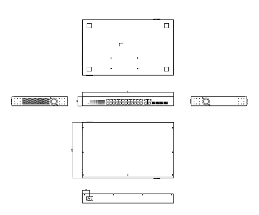
Technischical Details:
| Items | Specifications |
| Model No. | ALL-SG8428v2PM |
| Key Components | RTL8382M+RTL8218Dx2+RTL8214FC Flash IC:16MB DDR: 1Gb IP808ARx3 PSE controller |
| I/O ports | 24x GbE ports, RJ45 4 x port GbE SFP/RJ45 combo Reset Button: reset to default setting, re-start system |
| PoE ports | Port# 1~ 24 IEEE802.3at, IEEE802.3af |
| LED Define | PWR/SYS: Green LED
PoE Alert: Green LED
ALM: Red LED
Port LED: RJ45:
PoE:
SFP: - Off: disconnected or fail - Green: 100/1000Mbps connected - Blinking: data transmitting |
| HW feature | IEEE802.3 10BASE-T IEEE802.3u 100BASE-TX IEEE802.3ab 1000BASE-T IEEE802.3az EEE IEEE802.3x IEEE802.3z IEEE802.3at, IEEE802.3af MAC address Table: 8K Packet buffer size: 4.1M Jumbo Frame: 10K bytes 56Gbps switching capacity Forwarding rate: 41.66Mpps (64-byte package size) |
| Data Transfer Rate | Ethernet:10 Mbps (half duplex),20 Mbps (full duplex) Fast Ethernet:100 Mbps (half duplex),200 Mbps (full duplex) Giga Ethernet:2000 Mbps (full duplex) |
| PoE power pin-out | Alternative A (Pin 1,2/3,6) |
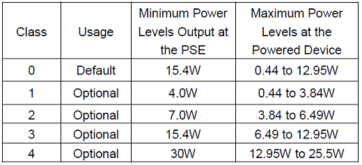
| PoE Output power capacity | Maximum output :30W per each port
|
| System Monitor | HW Monitor IC: ADT7476
|
| Power Input | Internal power supply Input: 100-240V AC Output: 450W |
| PoE Power Budget | 370W |
| Reset button | Support reset to default configuration |
| Dimension | 441(W) x 270(D) x 45(H) mm |
| FAN Design | 6300 Fanx2 (Smart Fan) |
| Temperature | Operating: -5~ 50? Storage : -40 ~ 70? |
| Humidity | Operating: 10% ~ 90% RH (non-condensing) Storage: 5% ~ 90% RH (non-condensing) |
-
- Software Feature
| Status | System Information |   |   |
| Logging Message |   |   | |
| Port | Statistics |   | |
| Error Disabled | |||
| Bandwidth Utilization |   | ||
| Link Aggregation |   | ||
| MAC Address Table | 8K |   | |
| Network | IP Address | Static / Dynamic |   |
| System Time | SNTP / From Computer / Manual Time |   | |
| Port | Port Setting | State / Speed / Duplex / Flow Control |   |
| Error Disabled | Recovery Interval | ACL / ARP Rate Limit / BPDU Guard / Broadcast Flood / DHCP Rate Limit / Port Security / Self Loop / Unicast Flood / Unknown Multicast Flood | |
| Link Aggregation | Group |   | |
| Port Setting | State / Speed / Flow Control | ||
| LACP |   | ||
| EEE |   |   | |
| Jumbo Frame | 9K Byte |   | |
| PoE | Global Setting | Schedule Status | |
| Priority Setting | |||
| Power Limit | |||
| Power Show | |||
| VLAN | VLAN | Create VLAN | |
| VLAN Configuration | |||
| Membership |   | ||
| Port Setting | |||
| Voice VLAN | Property | ||
| Voice OUI | |||
| Protocol VLAN | Protocol Group | ||
| Group Binding | |||
| MAC VLAN | MAC Group | ||
| Group Binding | |||
| Surveillance VLAN | Property | ||
| Surveillance OUI | |||
| GVRP | Property | ||
| Membership | |||
| Statistics | |||
| MAC Address Table | Dynamic Address | Aging Time |   |
| Static Address | |||
| Filtering Address |   |   | |
| Spanning Tree | Property | State / Operation Mode / Path Cost / BPDU Handling | Operation Mode : STP/RSTP/MSTP |
| Port Setting |   |   | |
| MST Instance | |||
| MST Port Setting | |||
| Statistics |   |   | |
| Discovery | LLDP | Property | |
| Port Setting |   | ||
| MED Network Policy | |||
| MED Port Setting | |||
| Packet View |   | ||
| Local Information |   | ||
| Neighbor |   | ||
| Statistics |   | ||
| Multicast | General | Property | Unknown Multicast Action / Multicast Forward Method |
| Group Address | |||
| Router Port | |||
| Forward All Table | |||
| Throttling | |||
| Filtering Profile | |||
| Filtering Binding | |||
| IGMP Snooping | Property | State / Version / Report Suppression | |
| Querier |   | ||
| Statistics |   | ||
| MLD Snooping | Property | State / Version / Report Suppression | |
| Statistics | |||
| MVR | Property | State / VLAN / Mode / Group Start / Group Count / Query Time | |
| Port Setting | |||
| Group Address | |||
| Security | RADIUS | ||
| TACACS+ | |||
| AAA | Method List | ||
| Login Authentication | Console / Telnet / SSH / HTTP / HTTPS | ||
| Management Access | Management VLAN |   | |
| Management Service | Telnet / SSH / HTTP / HTTPS / SNMP / Session Timeout | ||
| Management ACL | |||
| Management ACE | |||
| Authentication Manager | Property |   | |
| Port Setting | |||
| MAC-Based Local Account | |||
| WEB-Based Local Account |   | ||
| Sessions |   | ||
| Port Security |   |   | |
| Protected Port |   |   | |
| Storm Control |   | State / Broadcast / Unknown Multicast / Unknown Unicast / Action (Drop / Shutdown) | |
| DoS | Property |   | |
| Port Setting |   | ||
| Dynamic ARP Inspection | Property |   | |
| Statistics |   | ||
| DHCP Snooping | Property |   | |
| Statistics |   | ||
| Option82 Property |   | ||
| Option82 Circuit ID |   | ||
| IP Source Guard | Port Setting |   | |
| IMPV Binding |   | ||
| Save Database |   | ||
| ACL | MAC ACL |   |   |
| MAC ACE |   |   | |
| IPv4 ACL |   |   | |
| IPv4 ACE |   |   | |
| IPv6 ACL |   |   | |
| IPv6 ACE |   |   | |
|   | ACL Binding |   |   |
| QoS | General | Property | CoS / DSCP / CoS-DSCP / IP Precedence |
| Queue Scheduling | Strict Priority / WRR | ||
| CoS Mapping |   | ||
| DSCP Mapping |   | ||
| IP Precedence Mapping |   | ||
| Rate Limit | Ingress / Egress Port |   | |
| Egress Queue |   | ||
| Diagnostics | Logging | Property | Console / RAM / Flash |
| Remote Server |   | ||
| Mirroring |   |   | |
| Ping |   |   | |
| Traceroute |   |   | |
| Copper Test |   |   | |
| Fiber Module |   |   | |
| UDLD | Property | Message Time | |
| Neighbor |   | ||
| Management | User Account |   |   |
| Firmware | Upgrade / Backup | Action (Upgrade / Backup) / Method (TFTP / HTTP) | |
| Active Image | Active Image / Backup Image | ||
| Configuration | Upgrade / Backup | Action (Upgrade / Backup) / Method (TFTP / HTTP) | |
| Save Configuration | Source File / Destination File, Restore Factory Default | ||
| SNMP | View |   | |
| Group |   | ||
| Community |   | ||
| User |   | ||
| Engine ID |   | ||
| Trap Event | Authentication Failure / Link UP_Down / Cold Start / Warm Start | ||
| Notification |   | ||
| RMON | Statistics |   |   |
| History |   |   | |
| Event |   |   | |
| Alarm |   |   | |
| Marks | Safety | LVD EN62368-1:2014 |   |
| EMC | CE    EN55032: 2015+AC:2016 | class A | |
| FCC Part15, Subpart B: ANSI C |